By: FlySafe Research
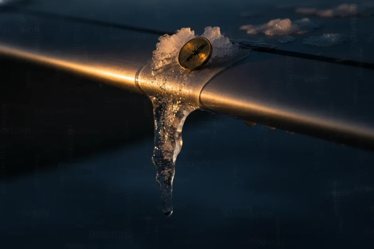
Ice accretion on a lifting surface remains one of the few flight hazards that can degrade aircraft performance silently, progressively, and in clear compliance with every published procedure. A wing certified to fly through known icing can still accumulate ice in patterns its protection system was never designed to shed. New sensing technology now under development aims to close that gap by measuring ice where it actually matters — on the wing surface itself, as it forms. FlySafe analysis shows that detection latency, not protection capacity, is frequently the limiting factor in icing-related performance loss, which is precisely the variable these sensors target.
Research discussed by Dr David Birch, associate professor of aerospace engineering at the University of Surrey, in Aerospace Testing International, centers on a sensing approach intended to improve how aircraft recognize ice accumulation before it reaches a performance-critical threshold. The implications extend across general aviation, regional turboprops, and large transport aircraft alike.
Why Ice on a Wing Changes the Aerodynamics
A wing generates lift by maintaining smooth, attached airflow over a carefully shaped surface. Ice accretion disrupts that geometry. Even contamination measured in fractions of a millimeter — roughly the texture of coarse sandpaper — can reduce maximum lift, increase drag, and raise the stall speed. The hazard is not the weight of the ice; it is the change in airflow.
Three accretion types are commonly distinguished:
- Rime ice forms from small supercooled droplets that freeze on contact, producing an opaque, rough deposit that follows the leading edge.
- Clear (glaze) ice forms when larger droplets spread before freezing, creating a dense, transparent layer that can build aft of the protected leading edge.
- Mixed ice combines both and is among the most difficult to address operationally.
A particular concern is the supercooled large droplet (SLD) regime. These droplets can strike the wing and run back beyond the area protected by leading-edge anti-ice systems, freezing on unprotected upper-surface skin. The 1994 ATR-72 accident at Roselawn, Indiana, investigated by the U.S. National Transportation Safety Board, became a defining case study in how ice forming aft of the protected zone can produce a sudden, asymmetric loss of control. Detailed icing physics and droplet behavior are documented by NASA's aircraft icing research program.
When and Where In-Flight Icing Concentrates
Airframe icing is governed by three coincident conditions: visible moisture, a temperature band that supports supercooled liquid water (typically between 0 °C and roughly −20 °C, with the most active range near 0 °C to −10 °C), and an aircraft flying through it. These conditions cluster in identifiable environments — frontal cloud systems, orographic lift over terrain, cumuliform buildups, and freezing precipitation layers near the surface during climb and approach.
Forecasting tools already flag these zones. AIRMET ZULU advisories, SIGMETs for severe icing, and graphical icing forecasts published by national meteorological services give crews probabilistic awareness before departure. Based on publicly available forecast products, dispatch and flight planning can route around the most active icing layers or select altitudes that minimize exposure. What these products cannot do is confirm, in the moment, how much ice a specific airframe has actually collected. That confirmation gap is where onboard sensing becomes decisive.
How Aircraft Detect and Shed Ice Today
Current ice protection falls into two functional categories, each with characteristic limits.
Detection is most often handled by a probe-type ice detector — commonly a small magnetostrictive rod mounted on the fuselage that vibrates at a known frequency. As ice accretes on the rod, its mass changes the resonant frequency, triggering an alert. These detectors are reliable, but they measure ice on the probe, not on the wing. Accretion rates on a probe and on a swept wing leading edge can differ, and the sensor's location may not represent the most exposed part of the airframe.
Protection systems then act on that information or on crew judgment:
- Pneumatic de-ice boots on the leading edge inflate to crack accumulated ice — standard on many turboprops.
- Bleed-air thermal anti-ice heats the leading edge continuously on most jet transports.
- Electro-thermal systems use embedded heating elements, increasingly common on newer composite-winged aircraft.
- Fluid (weeping wing / TKS) systems exude a freezing-point-depressant through porous panels, used widely in general aviation.
Each system is effective within its design envelope. The recurring weakness is timing and coverage: a crew may activate protection late, or ice may form in a runback pattern outside the heated or boot-protected zone. Regulatory guidance from the European Union Aviation Safety Agency treats this detection-and-response chain as a safety-critical sequence, not a single component.
What New Surface Sensing Changes
The research under development addresses the most direct measurement of all: the state of the wing surface itself. Rather than inferring accretion from a remote probe, surface-integrated sensing aims to detect the presence, location, and growth of ice directly on the aerodynamic surface — including areas where runback ice would otherwise go unobserved.
The operational value of this approach rests on three properties:
- Locality. Sensing on the wing, distributed across the surface, captures accretion where it degrades aerodynamics, not at a representative offset point.
- Latency. Real-time confirmation of ice growth lets protection systems be activated earlier and deactivated only when the surface is genuinely clear, improving both safety margin and energy efficiency.
- Coverage of unprotected zones. Detecting accretion aft of the leading edge directly addresses the SLD runback scenario that conventional probe detectors and leading-edge protection were never positioned to catch.
For composite and laminar-flow wing designs, where surface cleanliness is especially performance-sensitive, this granularity matters more than on older metal airframes. A sensing layer that reports the actual contamination state allows protection to be matched to the real condition of the wing rather than to a conservative assumption. Coverage of this work was published by Aerospace Testing International, which tracks emerging test and measurement technology across the sector.
Operational Implications for Airlines and Crews
A maturing surface-sensing capability would reshape several routine decisions, though certification and fleet integration are multi-year processes.
Recommendation: Until distributed surface sensing is certified and installed, crews should continue to treat existing probe detectors as indicators rather than complete pictures, and apply ice protection per the aircraft flight manual at the first indication of accretion — not after performance change is felt. Conservative use of anti-ice in known or forecast icing remains the established standard.
For dispatch and flight planning: Forecast icing layers should continue to inform altitude and route selection. Affected segments are typically those involving prolonged exposure in cloud near the freezing level, particularly during climb and holding. Earlier, more accurate onboard confirmation would, over time, reduce the conservatism premium currently built into icing avoidance, allowing more efficient profiles without reducing margins.
For maintenance and engineering: Surface-integrated sensors generate a data record of icing exposure that can support condition monitoring and fleet-level analysis of where and how icing is encountered in service — a dataset that supplements historical data analysis of icing-related events.
Key Takeaway
Aircraft icing has been understood for decades, yet it persists as a hazard precisely because the existing chain — detect, decide, protect — contains measurement gaps that conservative procedures can mask but not eliminate. Sensing technology that measures ice directly on the wing surface, in real time, attacks the weakest link in that chain. It does not replace anti-ice systems; it tells those systems, and the crew, the truth about the wing sooner and across a wider area. FlySafe analysis shows that closing detection latency is one of the highest-leverage improvements available in cold-weather flight safety.
FlySafe will continue to track the development, testing, and certification of distributed ice-sensing systems as they progress from research toward operational fleets, alongside the meteorological and operational factors that govern icing risk.
Analysis based on publicly available data only. This bulletin is informational and does not replace official aircraft flight manuals, manufacturer guidance, or regulatory directives.
- Detection latency — not the protection system's capacity — is the primary limiting factor in icing-related performance loss; new surface sensors target exactly this gap by measuring ice as it forms rather than after thresholds are exceeded.
- Supercooled large droplets (SLD) spread and freeze aft of leading-edge anti-ice coverage, on unprotected wing skin — the mechanism behind the 1994 Roselawn ATR-72 loss of control, and the scenario current protection systems were never designed to handle.
- The aerodynamic hazard of ice is not its weight but its geometry: contamination as thin as coarse sandpaper is enough to reduce maximum lift, increase drag, and raise stall speed.
Powered by B1KEY
Live tools behind the analysis.
The signals FlySafe writes about are also published live — continuously verified by the Sentinel pipeline.
Information is accurate as of the publication date. FlySafe uses exclusively publicly available data.